
Diagram 1: Capacitor voltage (VC) and current (I) waveforms
In a capacitor, current (I) flows across the capacitor leads the capacitor voltage (VC) by 90 degree (diagram 1). In another words, capacitor voltage (VC) lags the current (I) by 90 degree (diagram 1). This is because the voltage on a capacitor is directly proportional to the charge in the capacitor plates. The current must lead the voltage in time and phase in order to build up the charge in the capacitor plates and raise the capacitor voltage. This is proved in the series RC circuit (diagram 2) voltage waveforms (diagram 3).

Diagram 2: Series RC circuit
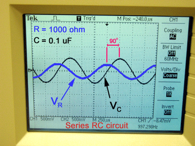
Diagram 3: Series RC circuit voltage waveforms
Digital Storage Oscilloscope (DSO) measures and displays AC and DC voltages signals over a wide range of frequencies. DSO does not measures current. When using the DSO to plot the capacitor voltage (VC) and resistor voltage (VR) on a series RC circuit (diagram 2) with a constant current, we can use the phasor diagram of a series RC circuit to conclude the relationship of the phase of current to the capacitor voltage (VC) and resistor voltage (VR).
Phasor diagram

Diagram 4: Phasor diagram of a series RC circuit
According to Kirchoff's current law, the current at any given instant in a series circuit must be the same throughout all parts of the circuit. Therefore, total current (IT) = resistor current (IR) = capacitor current (IC) as shown in the phasor diagram (diagram 4) of a series RC circuit (diagram 2).
Since current is the only quantity which is common to all parts of a series circuit, it is used as a reference for zero phase (positive x-axis) to show the phase relationships between currents and voltages.
Since the resistor current (IR) and resistor voltage (VR) are in phase (zero phase), the resistor voltage (VR) phasor will be on the same line on the positive x-axis. As the capacitor voltage (VC) lags the current by 90 degree, the capacitor voltage phase is a negative 90 degree.
Breadboard and DSO connection
It is not possible to measure directly the VR and VC values at the same time because they have different zero reference points or different grounds. To get VR, the "MATH" function of the DSO is used to subtract the signal at channel 2 (CH2) from the signal at channel 1 (CH1).

Diagram 5: Series RC circuit with channel probes of DSO

Diagram 6: Connection of series RC circuit on the breadboard
References:
[1] Phase relationships in AC circuits
[2] Wikipedia
[3] Electronics-Tutorials
[4] Basic electricity and electronics (By Charles A. Schuler and Richard J. Fowler)


1 comment:
It's a nice post about RC circuit. It's really useful, I like it :). Thanks for sharing it.
Post a Comment